
PLC (Programmable Logic Controller)
PLC is a digital electronic devices which have memory to store instructions to perform specific functions like sequence, logic, timing, counting and arithmetic operation to control machines and processes.
Initially these types of functions were done by different relay logics. which usually required large space and maintenance. Moreover those systems were not reliable. so with the thinking of the replacement of that Relay logic system the PLC came into existence.

The above figure is a very basic block diagram description of PLC. The main parts of PLC are:
a) Central Processing Unit: This is the main part of PLC which performs all the operations. This is the brain of PLC
b) Input and Output modules: This two modules are directly connected with the process. Input modules takes the status of different inputs from field and send the status of those to the processing module. The different inputs might be Push button, limit switch, ON/OFF switch, Motor contact etc.
According to the status of the input signals and the program written into the processor the PLC processor produces the output signal which ultimately goes to output device via the output modules. So the function of the output modules are to transmit the output signal from the processors to the output signal. The output device might be any type of ON/Off load or devices like solenoid valve, ON/OFF valve, pump, motor, light, fan etc.
C) Programmer: To operate the PLC there must have program to operate the PLC. That program must be written by some device which is called programmer. Those may be Laptop, Desktop or HMI. Program is written by the programmer and stored it into the processor RAM while PLC in ON for specific function.
D) Power Supply: Power supply is needed to the CPU as well as input output module. Supply voltage is 230 Voltage ac and 24 V dc is basically used for the input and output operation.
Basic Operation:
To perform a particular operation in plant by PLC first we have to write a program of that operation with suitable language using programmer. Then the program should be uploaded to the PLC. While PLC will be in RUN mode, it will check the status of different inputs and outputs. As per the program and these input output status PLC produces the output which is sent to the corresponding output devices via the output modeles.
Language uses in PLC programming:
Different PLC manufacturers use different language for programming. The most usable languages are;
*) Ladder
*) STL ( Statement List)
*) FBD (Functional Block Diagram)
Beyond this High level language like Fortran, Pascal, C, C++ etc might also be used for PLC programming.
Programming idea with Ladder:
I prefer Ladder to write the program. It is easy to understand. Ladder diagram looks like following figure.

It is the combination of inputs and outputs and the diagram looks like a ladder, which has two sides like a ladder called power rail, and from one power rail to another power rail the connection with different inputs and outputs is called Rung. There are many symbols in ladder language Normally Open input, Normally close input, Coil output, Latch output, Timer, Counter, Comparator. We will learn it while we will do the programming. Few symbols are given here.

Every symbol is available in the programming editor page. Just click on the symbol using drag and drop method we can write the program.
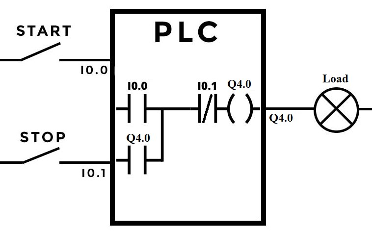
Each symbol indicates an input or output, rather each input and output are defined with symbol in the program. And each input and output must have an address. Normally input is address starts with English alphabet I and output starts with English alphabet Q like I0.0, Q4.0 etc. The notation 0.0 and 4.0 are not given arbitrary, it depends on the hardware where the corresponding input and output is connected with the input module terminal and output module terminal. (It needs a deep knowledge, i will do it later).
In short, say a start switch is connected with terminal no.I0.0 and a stop switch in connected with terminal no. I0.1 of input module. And say, a bulb or a motor is the load connected with Q4.0 of the output module which need to operate with these two switches. We can easily understand the wiring connection with PLC for this. We will have to write a program which will execute by the PLC to operate the output using that two switches.

So i am entering into the programming here.
P1) Write a program to start a motor using a start switch.

Here I0.0 is start switch and Q4.0 is the Motor. While the switch is pressed i.e. energized the status of I0.0 will be logic 1 and correspondingly the output Q4.0 will be logic 1 means Motor will be ON
P2) Write a program to start a motor using a start switch and stop the same Motor with a stop switch.

Here I0.1 is the Stop switch. Now it is very important to know how the Stop switch will be connected? When Start switch is operated the Motor should be ON, means the Stop switch should have logic 1 status though it is de-energized, means not operated. So, while Stop switch is not operated PLC getting logic 0 for this switch, which is required to convert to logic 1 and it is done in software level by using Normally close contact for stop switch. so when start switch is operated Motor Runs.
Now if Stop switch is operated PLC gets logic 1 which became logic 0 at software and Motor became Off ( as if Motor has disconnected from power source)
The above two program is OK if the switch is 'Maintained' type. There are two types of Push Button switches by operation, in industries. One is Maintained and another is Momentary. The Maintained switch remains pushed while push it, like the Bed Switch. And the Momentary switch remain push while pushing and came back to original state if release the push. In plant mainly Momentary switches are used. So if for the above two program if Momentary switches are used the Motor will not keep running and operation will not perfect. For that we have to use the latch operation, which is explained in the next program.
P3) Write a program to operate a Motor using Momentary Start and Stop switch.
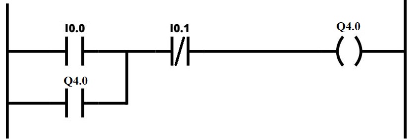
A status of output Q4.0 has been taken as input and it is used with Normally open contact ORing with the Start switch. While Start push button pressed, I0.0 is logic 1, and I0.1 is logic 1 ( as it is not operated), so the Output Q4.0 is logic high, Motor is ON. This logic 1 status of Q4.0 is applying at input before releasing the Start push button. So while Start push button is released, output Q 4.0 remains logic 1 as if it is getting power through input Q4.0 and I0.1 path. This is latching operation.
So using above program Motor will keep running while Start Push button is pressed once and released.
Now if we want to Stop the Motor, Just press the Stop push button for once and the Motor will stop.
******কখনো ছোট্ট ডোবাকে ভালো বেসো না । ডোবাকে করুণা কোরো কিন্তূ ভালোবেসো সমুদ্রকে । সমুদ্র তোমাকে তার বিশালতা দিয়ে প্রসারতা চেনাবে , আর ডোবা তোমাকে চেনাবে সংকীর্ণতা *****************
(I will go ahead very soon ----------- ক্ৰমশঃ ------🌹🌹🌹🌹🌹🌹🌹🌹🌹←←⅋𝔎𝔎Ⅲ)
PLC (Programmable Logic Controller)
 Reviewed by Susanta Pal
on
19:28
Rating:
Reviewed by Susanta Pal
on
19:28
Rating:
Reviewed by Susanta Pal
on
19:28
Rating:


No comments: